CNC Setups: FANUC 0T
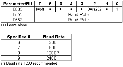
Hooking up the Fanuc 0T control to an RS-232 signal is done through a DB25 pin connector located below the tape reader on the control door. G-ZERO needs to be set for even parity, 7 data bits, and 1 stop bit with a recommended baud rate of 1200.
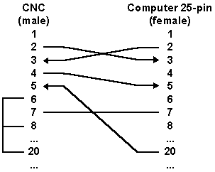
Note: If signals from pins #6, #8, and #20 at Fanuc
0T are not in use, they need to be jumped together. In the same way, if signals from pins
#4 and #5 are not in use, they need to be jumped together.
Pin Description
| CNC (25-pin) | Computer (25-pin) | Computer (9-pin) |
| 1 Frame Ground (FG) | 1 Not Connected | 1 Carrier Detect (CD) |
| 2 Send Data (SD) | 2 Send Data (SD) | 2 Receive Data (RD) |
| 3 Receive Data (RD) | 3 Receive Data (RD) | 3 Send Data (SD) |
| 4 Ready To Send (RTS) | 4 Ready To Send (RTS) | 4 Data Terminal Ready (DTR) |
| 5 Clear To Send (CTS) | 5 Clear To Send (CTS) | 5 Signal Ground (SG) |
| 6 Data Ready (DR) | 6 Data Ready (DR) | 6 Data Ready (DR) |
| 7 Signal Ground (SG) | 7 Signal Ground (SG) | 7 Ready To Send (RTS) |
| 8 Carrier Detect (CD) | 8 Carrier Detect (CD) | 8 Clear To Send (CTS) |
| ..... | ..... | 9 Ring Indicator (RI) |
| 20 Data Terminal Ready (DTR) | 20 Data Terminal Ready (DTR) |
Use cable with following connections
OPTIONAL - Hardware Handshake

Parameters
